Friday, April 20, 2018

Virtual Tunnel Interface – Cisco ASA


Virtual Tunnel Interface – Cisco ASA
About Virtual Tunnel Interfaces
The ASA supports a logical interface called Virtual Tunnel Interface (VTI). As an alternative to policy based VPN, a VPN tunnel can be created between peers with Virtual Tunnel Interfaces configured. This supports route based VPN with IPsec profiles attached to the end of each tunnel. This allows dynamic or static routes to be used. Egressing traffic from the VTI is encrypted and sent to the peer, and the associated SA decrypts the ingress traffic to the VTI.
Using VTI does away with the requirement of configuring static crypto map access lists and mapping them to interfaces. You no longer have to track all remote subnets and include them in the crypto map access list. Deployments become easier, and having static VTI which supports route based VPN with dynamic routing protocol also satisfies many requirements of a virtual private cloud.
Guidelines for Virtual Tunnel Interfaces
IPv6
·         IPv6 is not supported.
General Configuration Guidelines
·         You can use dynamic or static routes for traffic using the tunnel interface.
·         The MTU for VTIs is automatically set, according to the underlying physical interface.
·         VTI supports IKEv1 and uses IPsec for sending and receiving data between the tunnel's source and destination.
·         If Network Address Translation has to be applied, the IKE and ESP packets will be encapsulated in the UDP header.
·         IKE and IPsec security associations will be re-keyed continuously regardless of data traffic in the tunnel. This ensures that VTI tunnels are always up.
·         Tunnel group name must match what the peer will send as its IKEv1 identity.
·         For IKEv1 in LAN-to-LAN tunnel groups, you can use names which are not IP addresses, if the tunnel authentication method is digital certificates and/or the peer is configured to use aggressive mode.
·         VTI and crypto map configurations can co-exist on the same physical interface, provided the peer address configured in the crypto map and the tunnel destination for the VTI are different.
·         By default, all traffic through VTI is encrypted.
·         There are no security level configurations for VTI interfaces.
·         Access list can be applied on a VTI interface to control traffic through VTI.
·         Only BGP is supported over VTI.
Context Mode
Supported in single mode only.
Firewall Mode
Supported in routed mode only.
Create a VTI Tunnel
To configure a VTI tunnel, create an IPsec proposal (transform set). You will need to create an IPsec profile that references the IPsec proposal, followed by a VTI interface with the IPsec profile. Configure the remote peer with identical IPsec proposal and IPsec profile parameters. SA negotiation will start when all tunnel parameters are configured.
https://www.cisco.com/c/dam/en/us/td/i/templates/note.gifNote

For the ASA which is a part of both the VPN VTI domains, and has BGP adjacency on the physical interface:
When a state change is triggered due to the interface health check, the routes in the physical interface will be deleted until BGP adjacency is re-established with the new active peer. This behavior does not apply to logical VTI interfaces.

Procedure

Step 1  
Add an IPsec Proposal (Transform Sets).
Step 2  
Add an IPsec Profile.
Step 3  
Add a VTI Tunnel.

Add an IPsec Proposal (Transform Sets)
A transform set is required to secure traffic in a VTI tunnel. Used as a part of the IPsec profile, it is a set of security protocols and algorithms that protects the traffic in the VPN. Before You Begin
·         You can use either pre-shared key or certificates for authenticating the IKEv1 session associated with a VTI. You must configure the pre-shared key under the tunnel group used for the VTI.
·         For certificate based authentication using IKEv1, you must specify the trustpoint to be used at the initiator. For the responder, you must configure the trustpoint in the tunnel-group command.
Procedure
Add an IKEv1 transform set that defines how to protect the traffic, enter the following command:
crypto ipsec ikev1 transform-set transform-set-name encryption [authentication]


Example:
ciscoasa(config)#crypto ipsec ikev1 transform-set SET1 esp-aes esp-sha-hmac
Encryption specifies which encryption method protects IPsec data flows:
·         esp-aes—Uses AES with a 128-bit key.
·         esp-aes-192—Uses AES with a 192-bit key.
·         esp-aes-256—Uses AES with a 256-bit key.
·         esp-des—Uses 56-bit DES-CBC.
·         esp-3des—Uses triple DES algorithm.
·         esp-null—No encryption.
Authentication specifies which encryption method to protect IPsec data flows:
·         esp-md5-hmac—Uses the MD5/HMAC-128 as the hash algorithm.
·         esp-sha-hmac—Uses the SHA/HMAC-160 as the hash algorithm.
·         esp-none—No HMAC authentication.
Add an IPsec Profile
An IPsec profile contains the required security protocols and algorithms in the IPsec proposal or transform set that it references. This ensures a secure, logical communication path between two site-to-site VTI VPN peers.
Procedure

Step 1  
Set a name for the profile:
crypto ipsec profile name


Example:
ciscoasa(config)#crypto ipsec profile PROFILE1
Step 2  
Set the IKEv1 proposal. Enter the following command in the crypto ipsec profile command sub-mode:
set ikev1 transform set set_name
In this example, SET1 is the IKEv1 proposal set created previously.
ciscoasa(config-ipsec-profile)#set ikev1 transform-set SET1
Step 3  
(Optional) Specify the duration of the security association:
set security-association lifetime {seconds number | kilobytes {number | unlimited}}


Example:
ciscoasa(config-ipsec-profile)#set security-association lifetime
seconds 120 kilobytes 10000
Step 4  
(Optional) Configure the end of the VTI tunnel to act only as a responder:
responder-only
·         You can configure one end of the VTI tunnel to perform only as a responder. The responder-only end will not initiate the tunnel or rekeying.
Step 5  
(Optional) Specify the PFS group. Perfect Forward Secrecy (PFS) generates a unique session key for each encrypted exchange. This unique session key protects the exchange from subsequent decryption. To configure PFS, you have to select the Diffie-Hellman key derivation algorithm to use when generating the PFS session key. The key derivation algorithms generate IPsec security association (SA) keys. Each group has a different size modulus. A larger modulus provides higher security, but requires more processing time. You must have matching Diffie-Hellman groups on both peers.
set pfs {group1 | group2 | group5}


Example:
ciscoasa(config-ipsec-profile)#set pfs group2

Add a VTI Interface
To create a new VTI interface and establish a VTI tunnel, perform the following steps:
https://www.cisco.com/c/dam/en/us/td/i/templates/note.gifNote

Implement IP SLA to ensure that the tunnel remains up when a router in the active tunnel is unavailable. See Configure Static Route Tracking in the ASA General Operations Configuration Guide in http:/​/​www.cisco.com/​go/​asa-config.

Procedure

Step 1  
Create a new tunnel interface:
interface tunnel tunnel_interface_number


Example:
ciscoasa(config)#interface tunnel 100
Specify a tunnel ID, from a range of 0 to 100. Up to 100 VTI interfaces are supported.
Note   
If you will be migrating configurations from other devices to ASA 5506 devices, use the tunnel ID range of 1 - 100. This is to ensure compatibility of the tunnel range of 1 - 100 available in ASA 5506 devices.
Step 2  
Enter the name of the VTI interface.
Enter the following command in the interface tunnel command submode:
nameif interface name


Example:
ciscoasa(config-if)#nameif vti
Step 3  
Enter the IP address of the VTI interface.
ip address IP addressmask


Example:
ciscoasa(config-if)#ip address 192.168.1.10 255.255.255.254
Step 4  
Specify the tunnel source interface.
tunnel source interface interface name


Example:
ciscoasa(config-if)#tunnel source interface outside
Step 5  
Specify the tunnel destination IP address.
tunnel destination IP address


Example:
ciscoasa(config-if)#tunnel destination 10.1.1.1
Step 6  
Configure the tunnel with tunnel mode IPsec IPv4.
tunnel mode ipsec ipv4


Example:
ciscoasa(config-if)#tunnel mode ipsec ipv4
Step 7  
Assign the IPsec profile to tunnel.
tunnel protection ipsec IPsec profile


Example:
ciscoasa(config-if)#tunnel protection ipsec Profile1
This new VTI can be used to create an IPsec site-to-site VPN.


~ End-of-Document ~

Friday, April 13, 2018

Cisco ASA – Active / Active Failover

Usually when I’m asked to setup Active/Active I cringe, not because its difficult, its simply because people assume active/active is better than active/standby. I hear comments like ‘we have paid for both firewalls lets use them’, or ‘I want to sweat both assets’.
The only real practical use cases I can think of for Active /Active are;
  • You have a multi-tenancy environment and want to offer your tenants failover firewall capability.
  • You have multiple LAN subnets and what to split them though different firewalls.
What Active/Active Wont Give You
Load balancing: It’s a firewall! If you want load balancing buy a load balancer! People assume because both firewalls are passing traffic, they must load balance, they don’t, in fact they don’t even pass traffic from the same subnet.
VPNS: Yes theres no VPNs with Active Active. (This is 100% the case up to an including version 9.0, after version 9.0 they have stopped saying it’s not supported, but don’t say it’s supported).

Deploy Cisco ASA in Active/Active Failover

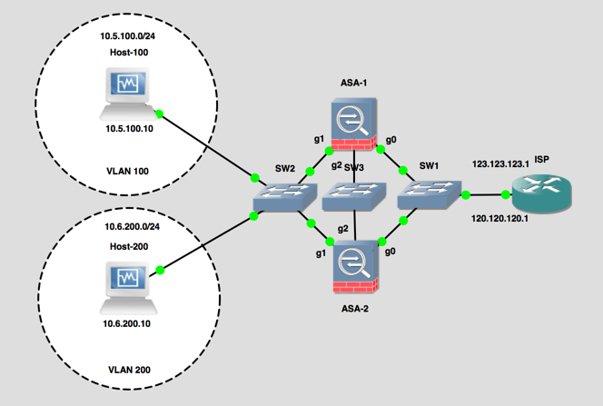
Here’s what Im going to setup;
Active Active ASA
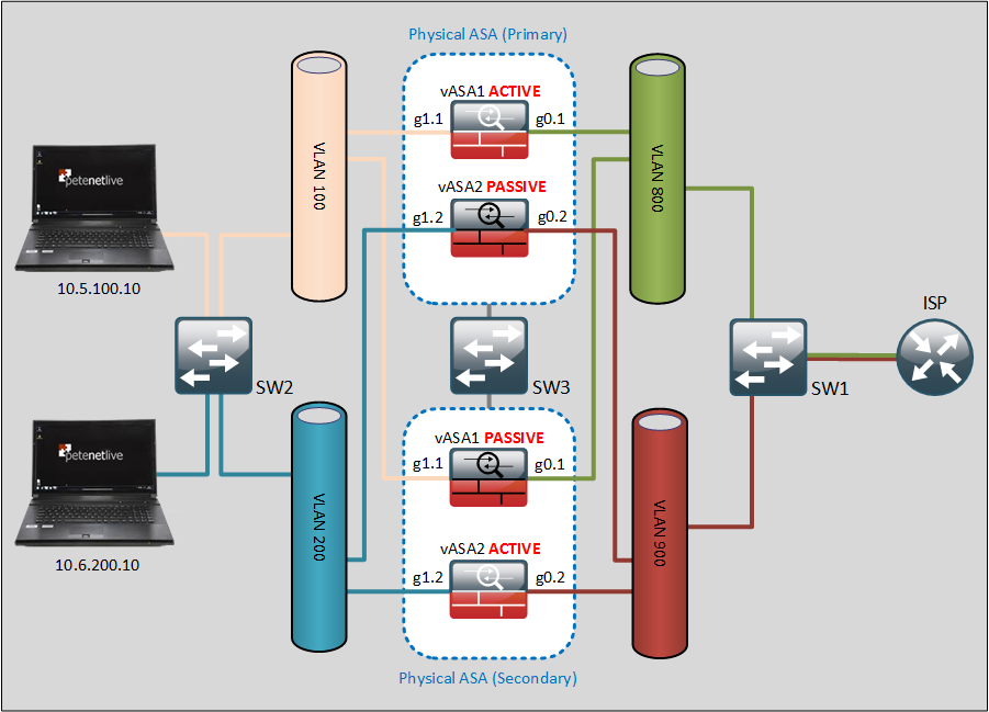
For a more ‘logical’ view heres what is actually being setup;
Logical Active Active ASA
1. Make sure the Licences are on the firewalls allow multiple contexts. and Active/Active, for 5510, 5512-X, and 5508-X that means Security Plus, for all other models a ‘base’ licence is required. (Note: This CANNOT be done on an ASA 5505 or 5506-X).
ciscoasa(config)# show version

Cisco Adaptive Security Appliance Software Version 8.4(2) 

——OUTPUT REMOVED FOR THE SAKE OF BREVITY—

Failover                          : Active/Active  perpetual
VPN-DES                           : Enabled        perpetual
VPN-3DES-AES                      : Disabled       perpetual
Security Contexts                 : 5              perpetual
GTP/GPRS                          : Disabled       perpetual

——OUTPUT REMOVED FOR THE SAKE OF BREVITY—

Configuration last modified by enable_15 at 08:04:40.249 UTC Wed Oct 14 2015
ciscoasa(config)#

2. Put the firewalls in Multiple context mode.
ciscoasa(config)# mode multiple 
WARNING: This command will change the behavior of the device
WARNING: This command will initiate a Reboot
Proceed with change mode? [confirm] 
Convert the system configuration? [confirm] 
!
The old running configuration file will be written to flash

Converting the configuration - this may take several minutes for a large configuration

The admin context configuration will be written to flash

The new running configuration file was written to flash
Security context mode: multiple 
3. Let it reboot.
4. Make sure the firewall is in routed mode, and multiple context mode, repeat on the other firewall.
ciscoasa> enable
Password: *********
ciscoasa# show mode
Security context mode: multiple 
ciscoasa# show firewall
Firewall mode: Router
ciscoasa#
5. Once ASA1 is backup give it a sensible hostname, and ensure all the physical interfaces (and any sub interfaces) are NOT shutdown, and add then to the relevant VLAN (they are shut down by default).
ciscoasa(config)# hostname PHYSICAL-ASA    
PHYSICAL-ASA(config)# interface gigabitEthernet 0
PHYSICAL-ASA(config-if)# no shut
PHYSICAL-ASA(config)# interface gigabitEthernet 0.1
PHYSICAL-ASA(config-subif)# no shut
PHYSICAL-ASA(config-subif)# vlan 800
PHYSICAL-ASA(config)# interface gigabitEthernet 0.2
PHYSICAL-ASA(config-subif)# no shut
PHYSICAL-ASA(config-subif)# vlan 900
PHYSICAL-ASA(config)# interface gigabitEthernet 1
PHYSICAL-ASA(config-if)# no shut
PHYSICAL-ASA(config-if)# interface gigabitEthernet 1.1
PHYSICAL-ASA(config-subif)# no shut
PHYSICAL-ASA(config-subif)# vlan 100
PHYSICAL-ASA(config-subif)# interface gigabitEthernet 1.2
PHYSICAL-ASA(config-subif)# no shut
PHYSICAL-ASA(config-subif)# vlan 200
PHYSICAL-ASA(config-subif)# exit
PHYSICAL-ASA(config)# exit
PHYSICAL-ASA# 
6. Failover link NEEDS to be configured and used by the SYTEM Context, so its configured here. (Note: I’m using the same physical interface for LAN and Stateful failover information).
PHYSICAL-ASA(config)# failover lan unit primary
PHYSICAL-ASA(config)# failover lan interface FAILOVER GigabitEthernet2
INFO: Non-failover interface config is cleared on GigabitEthernet2 and its sub-interfaces
PHYSICAL-ASA(config)# failover link FAILOVER GigabitEthernet2
PHYSICAL-ASA(config)# failover interface ip FAILOVER 172.16.1.1 255.255.255.0 standby 172.16.1.2
PHYSICAL-ASA(config)#
7. You can only have TWO failover groups (you can have many contexts, depending on the licence on your firewall).
PHYSICAL-ASA(config)# failover group 1
PHYSICAL-ASA(config-fover-group)# polltime interface msec 500 holdtime 5
PHYSICAL-ASA(config-fover-group)# primary 
PHYSICAL-ASA(config-fover-group)# preempt 100
PHYSICAL-ASA(config-fover-group)# exit
PHYSICAL-ASA(config)# failover group 2
PHYSICAL-ASA(config-fover-group)# polltime interface msec 500 holdtime 5
PHYSICAL-ASA(config-fover-group)# secondary 
PHYSICAL-ASA(config-fover-group)# preempt 200
Note: Unlike Active/Passive the ASA can preempt and ‘fail-back’ automatically.
8. Setup and assign your CONTEXTS (virtual firewalls), to these groups.
PHYSICAL-ASA(config)# admin-context admin    
PHYSICAL-ASA(config)# context admin
PHYSICAL-ASA(config-ctx)# config-url disk0:/admin.cfg

Cryptochecksum (changed): d9951253 3b82d2ce 840166f8 ccd3d7f1 
INFO: Context admin was created with URL disk0:/admin.cfg
INFO: Admin context will take some time to come up .... please wait.
PHYSICAL-ASA(config-ctx)# context vASA1
Creating context 'vASA1'... Done. (2)
PHYSICAL-ASA(config-ctx)# allocate-interface GigabitEthernet1.1 inside_vASA1
PHYSICAL-ASA(config-ctx)# allocate-interface GigabitEthernet0.1 outside_vASA1
PHYSICAL-ASA(config-ctx)# config-url disk0:/vASA1.cfg

WARNING: Could not fetch the URL disk0:/vASA1.cfg
INFO: Creating context with default config
PHYSICAL-ASA(config-ctx)# join-failover-group 1
PHYSICAL-ASA(config-ctx)# context vASA2
Creating context 'vASA2'... Done. (3)
PHYSICAL-ASA(config-ctx)# allocate-interface GigabitEthernet1.2 inside_vASA2 
PHYSICAL-ASA(config-ctx)# allocate-interface GigabitEthernet0.2 outside_vASA2
PHYSICAL-ASA(config-ctx)# config-url disk0:/vASA2.cfg                        

WARNING: Could not fetch the URL disk0:/vASA2.cfg
INFO: Creating context with default config
PHYSICAL-ASA(config-ctx)# join-failover-group 2
The following will show you a summary of the contexts.
PHYSICAL-ASA(config)# show run | b context
admin-context admin
context admin
  config-url disk0:/admin.cfg
!

context vASA1
  allocate-interface GigabitEthernet0.1 outside_vASA1 
  allocate-interface GigabitEthernet1.1 inside_vASA1 
  config-url disk0:/vASA1.cfg
  join-failover-group 1
!

context vASA2
  allocate-interface GigabitEthernet0.2 outside_vASA2 
  allocate-interface GigabitEthernet1.2 inside_vASA2 
  config-url disk0:/vASA2.cfg
  join-failover-group 2
!
10. Now configure vASA1.
PHYSICAL-ASA(config)# changeto context vASA1
PHYSICAL-ASA/vASA1(config)# interface outside_vASA 1
PHYSICAL-ASA/vASA1(config-if)# nameif outside
INFO: Security level for "outside" set to 0 by default.
PHYSICAL-ASA/vASA1(config-if)# ip address 123.123.123.123 255.255.255.0 standby 123.123.123.124
PHYSICAL-ASA/vASA1(config-if)# no shut
PHYSICAL-ASA/vASA1(config)# interface inside_vASA 1
PHYSICAL-ASA/vASA1(config-if)# nameif inside
INFO: Security level for "inside" set to 100 by default.
PHYSICAL-ASA/vASA1(config-if)# ip address 10.5.100.1 255.255.255.0 standby 10.5.200.2
PHYSICAL-ASA/vASA1(config-if)# no shut
PHYSICAL-ASA/vASA1(config-if)# exit
PHYSICAL-ASA/vASA1(config)# route outside 0.0.0.0 0.0.0.0 123.123.123.1
PHYSICAL-ASA/vASA1(config)# monitor-interface inside 
PHYSICAL-ASA/vASA1(config)# monitor-interface outside
PHYSICAL-ASA/vASA1(config)# object network obj_any
PHYSICAL-ASA/vASA1(config-network-object)# subnet 0.0.0.0 0.0.0.0
PHYSICAL-ASA/vASA1(config-network-object)# nat (inside,outside) dynamic interface
PHYSICAL-ASA/vASA1(config-network-object)# exit
PHYSICAL-ASA/vASA1(config)# exit
PHYSICAL-ASA/vASA1# 
11. Now configure vASA2.
PHYSICAL-ASA/vASA1(config)# changeto context vASA2
PHYSICAL-ASA/vASA2(config)# interface inside_vASA 2
PHYSICAL-ASA/vASA2(config-if)# nameif inside
INFO: Security level for "inside" set to 100 by default.       
PHYSICAL-ASA/vASA2(config-if)# ip address 10.6.200.1 255.255.255.0 standby 10.6.200.2
PHYSICAL-ASA/vASA2(config-if)# no shut              
PHYSICAL-ASA/vASA2(config)# interface outside_vASA 2
PHYSICAL-ASA/vASA2(config-if)# nameif outside
INFO: Security level for "outside" set to 0 by default.
PHYSICAL-ASA/vASA2(config-if)# ip address 120.120.120.120 255.255.255.0 standby 120.120.120.122
PHYSICAL-ASA/vASA2(config-if)# exit
PHYSICAL-ASA/vASA2(config)# route outside 0.0.0.0 0.0.0.0 120.120.120.1
PHYSICAL-ASA/vASA2(config)# object network obj_any
PHYSICAL-ASA/vASA2(config-network-object)# subnet 0.0.0.0 0.0.0.0
PHYSICAL-ASA/vASA2(config-network-object)# nat (inside,outside) dynamic interface
PHYSICAL-ASA/vASA2(config-network-object)# exit
PHYSICAL-ASA/vASA2(config)# 
12. Go back the the System context and save ALL the changes.
PHYSICAL-ASA/vASA2(config)# changeto system 
PHYSICAL-ASA(config)# wr mem all
Building configuration...
Saving context :           system : (000/003 Contexts saved) 
Cryptochecksum: e63d00e3 18224da1 be9d77c6 27c6e54d 

2109 bytes copied in 0.300 secs
Saving context :            admin : (001/003 Contexts saved) 
Cryptochecksum: f2f07827 f2784851 89925ac1 86c1e96f 

974 bytes copied in 0.330 secs
Saving context :            vASA1 : (002/003 Contexts saved) 
Cryptochecksum: 037e3a39 fe10e4d0 ff72d306 36fcf1ed 

1930 bytes copied in 0.330 secs
Saving context :            vASA2 : (003/003 Contexts saved) 
Cryptochecksum: e9024f22 53ad6316 70f7ccad 4394c81c 

1879 bytes copied in 0.230 secs
[OK]                                                         
PHYSICAL-ASA(config)# 
Note: Configuration on the main (physical) firewall is complete, the ‘failover’ configuration needs to now be setup on the second physical ASA.
13. On the ’Secondary’ Physical ASA.
ciscoasa# configure terminal 
ciscoasa(config)# interface gigabitEthernet 0
ciscoasa(config-if)# no shut
ciscoasa(config-if)# interface gigabitEthernet 0.1
ciscoasa(config-subif)# no shut
ciscoasa(config-subif)# vlan 800
ciscoasa(config-subif)# interface gigabitEthernet 0.2
ciscoasa(config-subif)# no shut
ciscoasa(config-subif)# vlan 900
ciscoasa(config-subif)# interface gigabitEthernet 1
ciscoasa(config-if)# no shut
ciscoasa(config-if)# interface gigabitEthernet 1.1
ciscoasa(config-subif)# no shut
ciscoasa(config-subif)# vlan 100
ciscoasa(config-subif)# interface gigabitEthernet 1.2
ciscoasa(config-subif)# no shut
ciscoasa(config-subif)# vlan 200
ciscoasa(config-subif)# exit
ciscoasa(config)# failover lan unit secondary 
ciscoasa(config)# failover lan interface FAILOVER GigabitEthernet2       
INFO: Non-failover interface config is cleared on GigabitEthernet2 and its sub-interfaces
ciscoasa(config)# failover link FAILOVER GigabitEthernet2                     
ciscoasa(config)# failover interface ip FAILOVER 172.16.1.1 255.255.255.0 standby 172.16.1.2
ciscoasa(config)# 
14. Remember failover is off by default, and we have not switched it on, this needs to be done on both of the physical ASA’s (primary and secondary). Note: Make sure the ‘failover’ interface is NOT in a shut down state first!
Secondary


ciscoasa(config)# interface GigabitEthernet2
ciscoasa(config)# no shut
ciscoasa(config)# failover
ciscoasa(config)# 

Primary

PHYSICAL-ASA(config)# int gigabitEthernet 2
PHYSICAL-ASA(config-if)# no shut
PHYSICAL-ASA(config)# failover
PHYSICAL-ASA(config)#
Note: If building in GNS3 sometimes you need to put a switch in the middle of the ‘backup link’ or the firewalls don’t detect each other!
17. Top Tip: Remember that you need to make the changes on the active firewall context in the correct failover group. Change the firewall prompt to show you all this information.
PHYSICAL-ASA# conf t
PHYSICAL-ASA(config)# prompt hostname context priority state
PHYSICAL-ASA/pri/act(config)# 

Testing Active/Active Failover

If you change to vASA1 (notice it’s active).
PHYSICAL-ASA/pri/act(config)# changeto context vASA1
PHYSICAL-ASA/vASA1/pri/act(config)# 
Now change to vASA2, (This ones in standby so DONT make changes here or they wont get replicated / saved).
PHYSICAL-ASA/vASA1/pri/act(config)# changeto context vASA2
PHYSICAL-ASA/vASA2/pri/stby(config)# 
Note: Moral of the story is you need to be aware what physical firewall you are on (primary or secondary) what mode you are in (active or standby) and what context you are in (vASA1 or vASA2). So in this example to make a change to vASA2 you would need to go to Secondary/Standby/vASA2 to edit the active firewall, (confusing eh! That’s why I change the firewall prompt).
Now you will want to test things, probably by pinging, don’t forget ICMP is not enabled by default an you will need to enable it, (in each context).
vASA1 (as specified above), make sure it says ‘act’ on the end of the prompt.

PHYSICAL-ASA/pri/act(config)# changeto context vASA1
PHYSICAL-ASA/vASA1/pri/act(config)# policy-map global_policy
PHYSICAL-ASA/vASA1/pri/act(config-pmap)# class inspection_default
PHYSICAL-ASA/vASA1/pri/act(config-pmap-c)# inspect icmp
PHYSICAL-ASA/vASA1/pri/act(config-pmap-c)# exit
PHYSICAL-ASA/vASA1/pri/act(config-pmap)# exit
PHYSICAL-ASA/vASA1/pri/act(config)# exit
PHYSICAL-ASA/vASA1/pri/act# 

vASA2 (as specified above), make sure it says ‘act’ on the end of the prompt.

PHYSICAL-ASA/sec/stby# changeto context vASA2
PHYSICAL-ASA/vASA2/sec/act# conf t
PHYSICAL-ASA/vASA2/sec/act(config)# policy-map global_policy
PHYSICAL-ASA/vASA2/sec/act(config-pmap)# class inspection_default
PHYSICAL-ASA/vASA2/sec/act(config-pmap-c)# inspect icmp
PHYSICAL-ASA/vASA2/sec/act(config-pmap-c)# exit
PHYSICAL-ASA/vASA2/sec/act(config-pmap)# exit
PHYSICAL-ASA/vASA2/sec/act(config)# exit

Sunday, February 11, 2018

ERROR: Cannot remove connected route

ERROR: Cannot remove connected route


firewall-asa(config)# no route INSIDE 192.168.0.0 255.255.255.0 172.16.0.5
ERROR: Cannot remove connected route
firewall-asa(config)#
The above error is caused when you try to route a directly connected interface to another subnet. In order to remove this route, you need to shutown the interface, then remove the route.
For example, if you have 172.16.0.0/24 assigned to your INSIDE interface, and 192.168.0.0/24 routed to an IP within 172.16.0.0, and you want to move 192.168.0.0/24 to a dedicated segment on the FW (say DMZ), you will run into this problem. You need to shutdown the INSIDE segment in order to remove the route.

firewall-asa(config)# interface Ethernet0/1
firewall-asa(config-subif)# shut
firewall-asa(config-subif)# exit
firewall-asa(config)#
firewall-asa(config)# no route INSIDE 192.168.0.0 255.255.255.0 172.16.0.5
firewall-asa(config)#
firewall-asa(config)# interface Ethernet0/1.100
firewall-asa(config-subif)# no shut
Problem solved.